In-Fixture Electronics

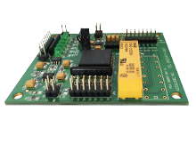
Multi Clock Divider Board
MCD can accept a wide frequency bandwidth for the testing of signal-generating devices such as crystals and oscillators.
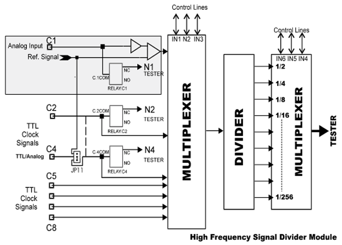
MCD8 operates by dividing down the input signal to fall within the measurement range of the test system. The divide sequence is selectable using onboard jumpers or programmable by the tester pins under software control. The MCD supports up to 7 different TTL & 1 programmable threshold input at frequencies in excess of 100 MHz. This includes CMOS, ECL, PECL, TTL, and analog signals (range of +/- 5V).
The divide sequence programmable range is 1/2, 1/4, 1/8, 1/16, 1/32, 1/64, 1/128 and 1/256. During the oscillator test, the high-frequency module can be totally isolated from the tester to minimize the impact of the system capacitance on measurement.


Relay Expander Module
Modes Of Operation
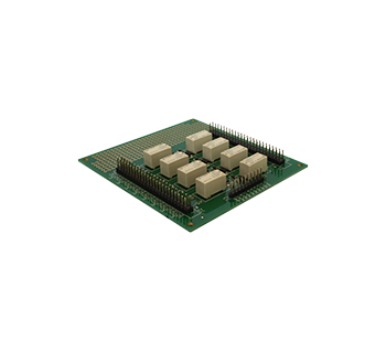
The REM-08 imposes a minimal requirement on the resources of the main system controller or the Automated Test Equipment (ATE). To operate in the POWER ON mode, the only requirements are +5V for the power input and 5 signals for the full control of 8 relays or 6 signals for the control of 16 relays. Two REM-08s can operate in Master/Slave configuration, which doubles the number of relays (to 16) and only requires 1 additional control line.
In POWER OFF applications, the REM-08 can be used through a dedicated connector with only one control line per relay (this port is also accessible in POWER ON mode for enhanced control).
The REM-08 has latching-type relays, which maintain a setting even through complete power up & down cycles.
Inputs and Outputs:
The REM-08 is designed with 8 double pole/double throw relays, which can switch 16 inputs to 32 outputs (or 32 inputs to 16 outputs). These numbers can be doubled by combining two REM-08s in a Master/Slave mode.
Current Ratings:
Power Requirements:
Power Requirements The REM-08 requires +5V external power to operate, the on-board switching power supply generates the -5V required. The normal power consumption of REM-08 is about 500mW except during the clocking of the relays where it can increase up to 2W. However, this is only for 40-60 m seconds. To eliminate any EMI that the on-board switching power supply may generate power is only applied during the initialization and configuration of the relays.
