FLYING PROBE TEST SYSTEM
THE MOST CONFIGURABLE FLYING PROBER ON THE MARKET.


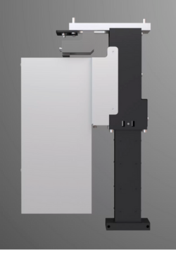
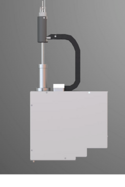
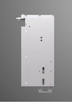
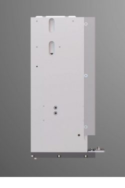
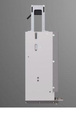
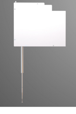
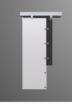
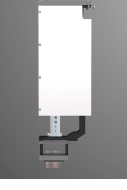
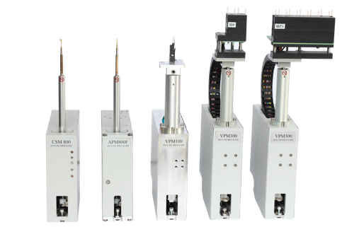
PROBE MODULE TYPES |
|
|
|||
|
|
Camera Module for fiducial detections & optical inspection |
LED Analyzer Module detects LED color and intensity |
Barcode Reader Module reads board and component barcodes |
||
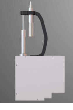
LaserScan Module (50 mm range) profiles PCB warpage for active warp compensation |
LaserScan Module (100 mm range) profiles PCB warpage for active warp compensation |
C-Scan Prode Module offers vectorless testing of open pins on connectors & ICs |
Thermoscan Camera Module for thermal analysis of components |
|
|
|
Flying Oscilloscope Probe Module for automated oscilloscope probing, enhancing the accuracy and depth of testing electronic components. |
Flying Fixture Module is a mini-fixture for bed-of-nails testing & high frequency measurements |
Marker Module marks boards "Pass" or "Fail" based on the test outcome |
RF Probe Module for high-speed digital and RF ATE production requirements. |
||
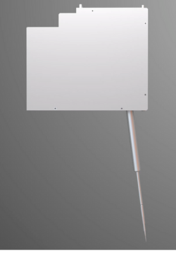 General Probe Module

Advanced Probe Module Technology

Ultra-Accurate Probing & Positioning System
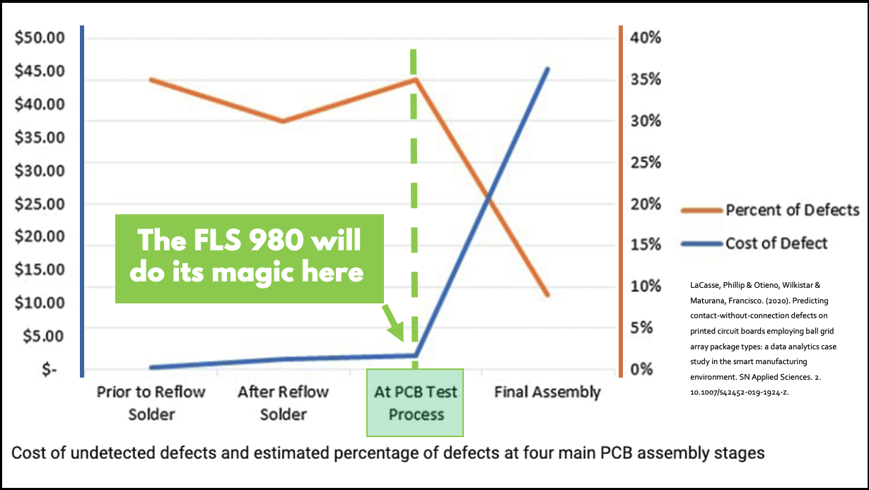
Closed-loop drives for shuttles and probe modules ensure precise and repeatable positioning of the probes. Riding on a 12-micron air gap, shuttles travel friction-free and without mechanical contact on the stator plane, thus operating without wear.High-resolution fiducial detection cameras, precise lighting, and advanced image processing software ensure precise and repeatable detection of fiducial marks on the UUT, as well as correct compensation for any offsets. Once the camera system locates the board in the X and Y planes, the LaserScan module is used to complete the 3D contour map of the board in the Z-plane.On-board Device ProgrammingThe electronic measurement system relies on precision circuits and components for reliable and repeatable measurements.Soft Touch Probing – The Integrator Pro™ system control software, with sophisticated motion control and measurement algorithms, ensures robust and repeatable operation.The FLS 980 Catches Defects Before It’s Too Late
The Flexibility of the FLS 980Dxi
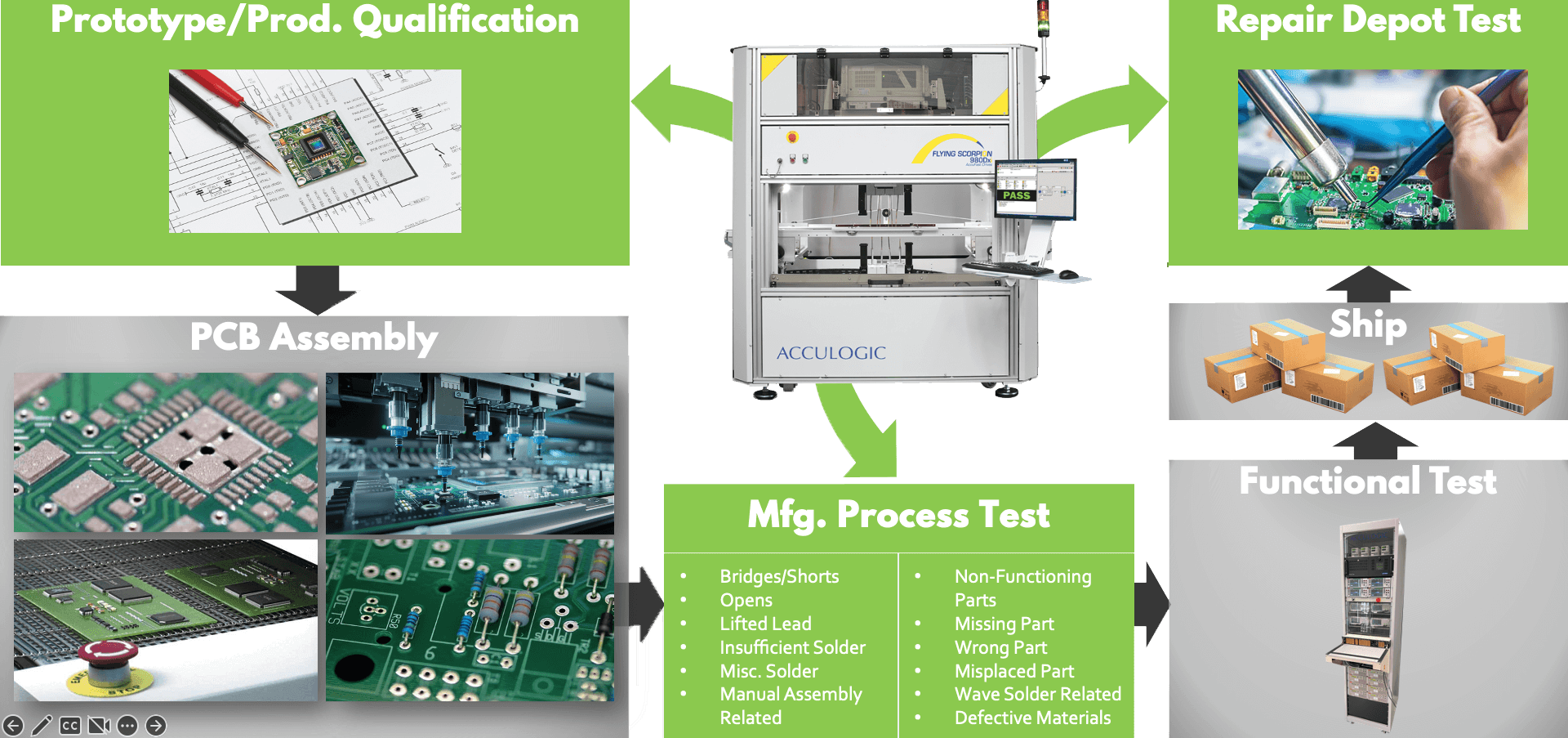
The Scorpion Flying Probe Tester is an effective testing solution that can be used throughout a circuit board's lifecycle. During the prototype testing phase, flying probe testers can quickly and accurately test small production runs, enabling engineers to identify and correct any issues before proceeding with full-scale production. In production testing, flying probe testers can provide high-speed and accurate testing for medium to high-volume production runs. And in repair depot testing, flying probe testers can help diagnose issues with boards that have failed in the field, minimizing downtime and reducing repair costs.
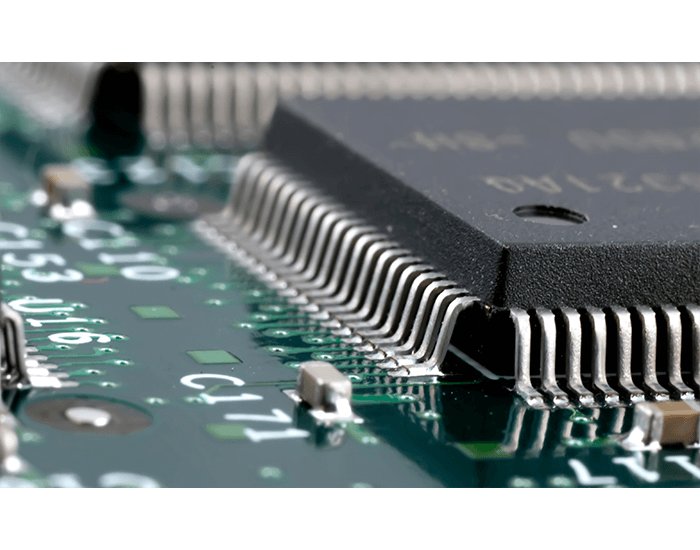
 SMD Device Leads
Test Pads, Vias, Thru-hole
Resistors, Caps., Diodes, Transistors
J-Lead Device Pins
Connector Pins, Tail & Tip
SMD Device Leads
Test Pads, Vias, Thru-hole
Resistors, Caps., Diodes, Transistors
J-Lead Device Pins
Connector Pins, Tail & Tip
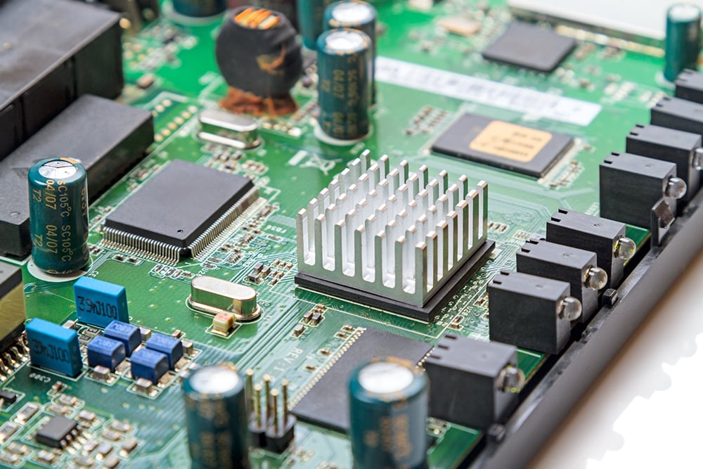
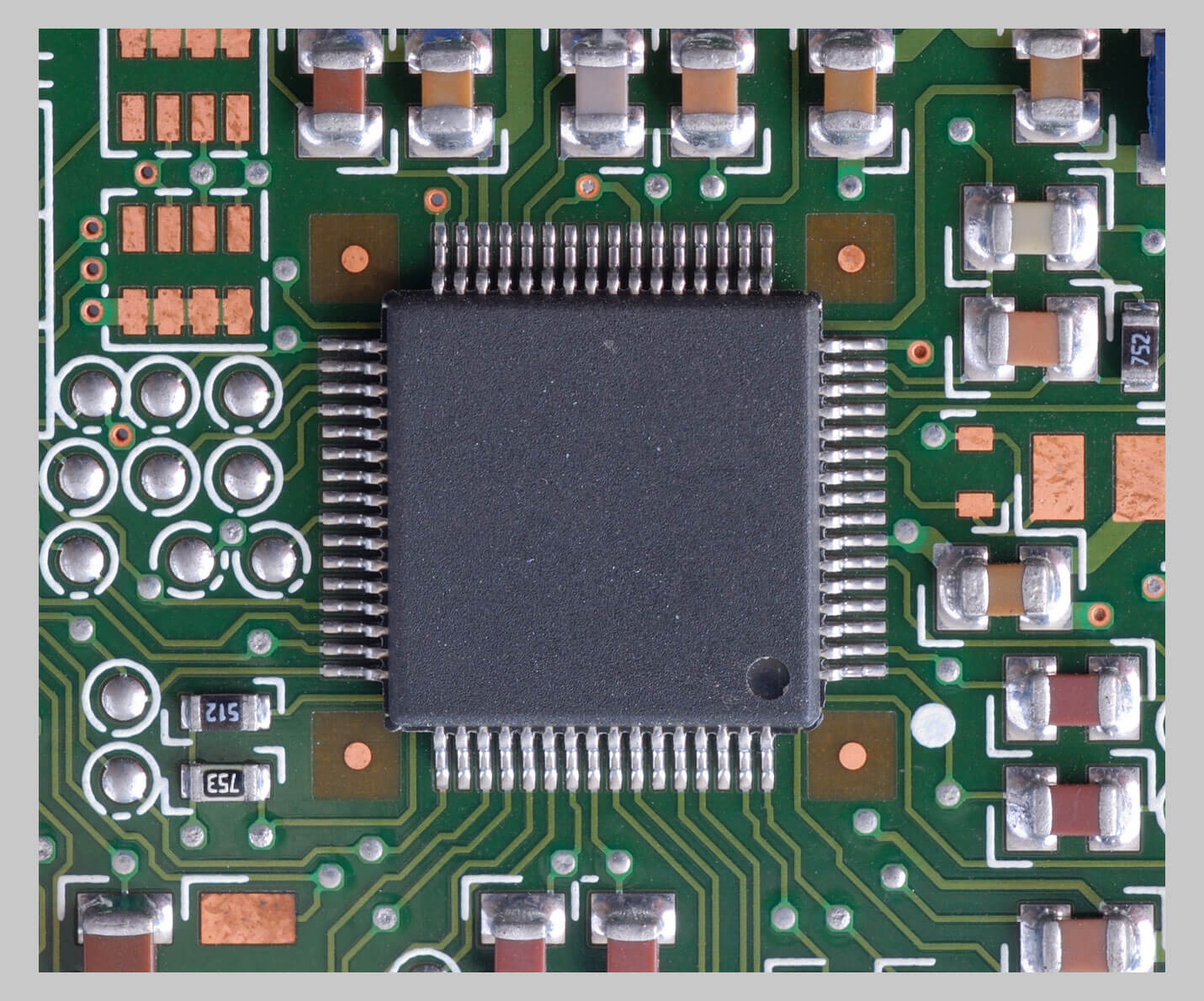
 Open pin faults on ICs & BGAs including ungrounded metal caps and heat sinks
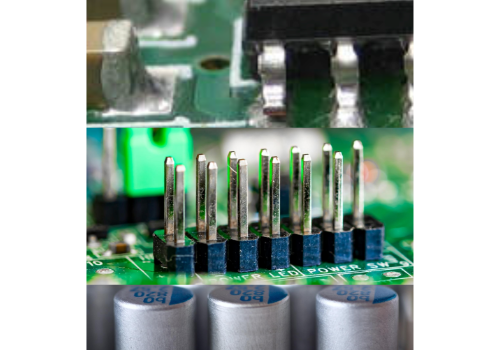
Connector pin faults - horizontal & perpendicular
Reversed electrolytic capacitors
Open pin faults on ICs & BGAs including ungrounded metal caps and heat sinks
Connector pin faults - horizontal & perpendicular
Reversed electrolytic capacitors
Boundary Scan/JTAG Test


On-Board Device Programming

Optical & Thermal Inspection Capabilities
Automated Optical Inspection & Microscopy
 check for the presence, absence, orientation, and polarity of componentsread 2D & 3D barcodes
LED test
check the hue, saturation, and intensity of SMT or edge-mounted LEDsread 2D & 3D barcodesThermal profile verification
LaserScan will map the board's z-height in as many locations as the user requires, to accurately determine the position of the UUT to within +/- 50 micrometers in the z-axis. So, LaserScan prevents any probing inaccuracies resulting from board warpage.
Flying Fixture
A small Bed of Nails mounted on a shuttle is used for:
High current power up & functional test
High-frequency test applications
Flash programming
Fast Boundary Scan test
Other complex test applications
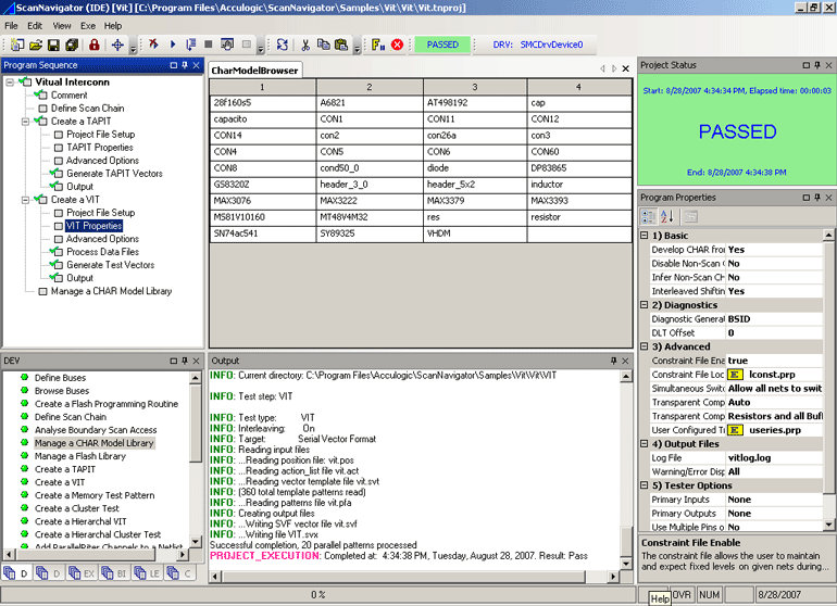
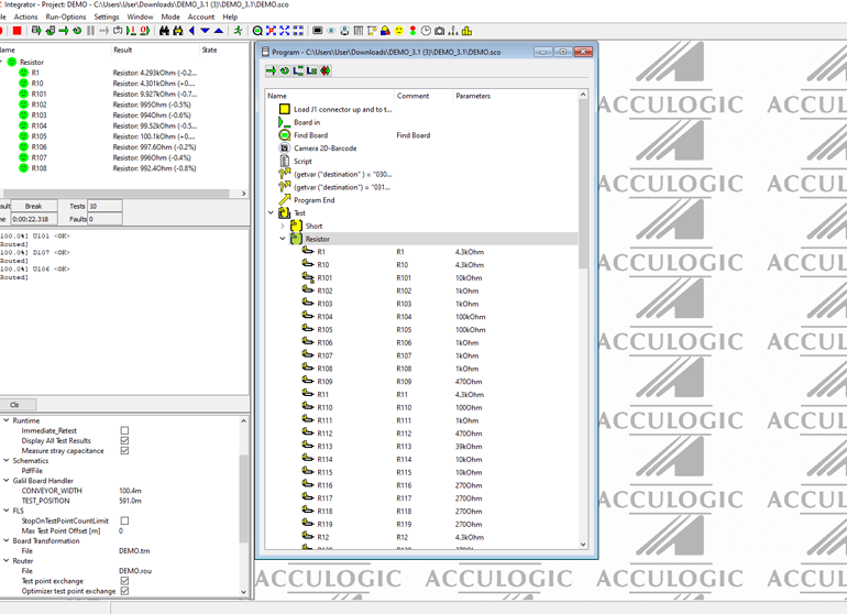
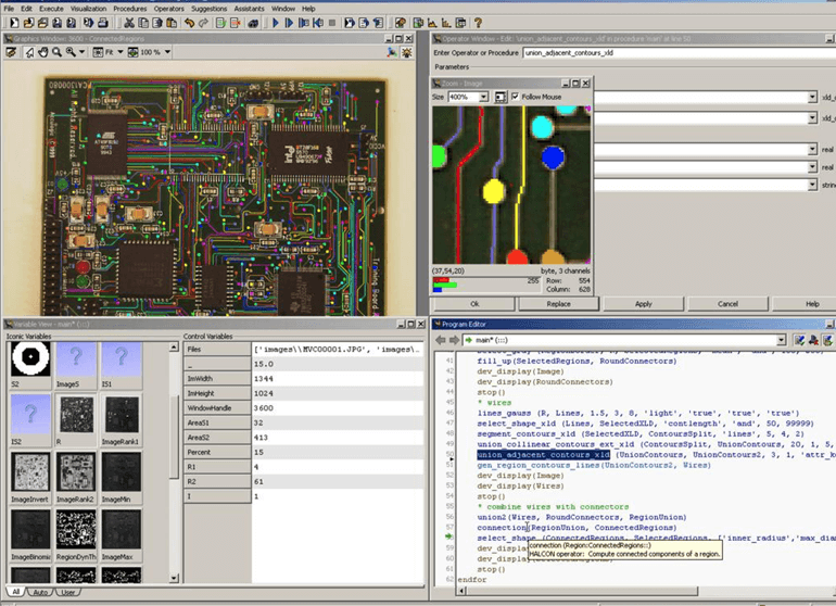
Test program generation for the FLS980 test platform is highly automated, simple, and intuitive. The automatic test program generator and operating software (INTEGRATOR) manages all aspects of test program and moves you quickly from test program development to production test deployment.
 INTEGRATOR includes: Acculogic's XMatic™ software, which automatically generates output files for most commercial In-Circuit, Flying Probe, Boundary Scan/JTAG testers, and AOI machines. With its user-guided nail/probe selection routine and complementary interactive tools, XMatic offers complete flexibility and control during fixture design and flying probe selection.
The FLS980DXi is an automated low-cost alternative to manual or semi-automated reverse engineering methods.
Intelligently maps board connectivity through probing pads on the boardRecreates netlist for test program generationGeneration of input data for test program developmentGeneration of electrical design dataAides the design of a new revision boardAccessibility to both sides of the PCBFast learn process with multiple probing in one passSoft touch probing reduces wear on learned PCB contact pointsLearn time reduction with increased probe countIntegrated software tools minimize processing time