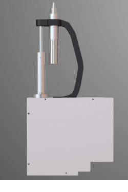
THE SCORPION FLS980E FLYING PROBE TEST SYSTEM
IT'S HOW YOU MAKE TEST WORK FOR YOU!
Unmatched test coverage
One tester for all product lifecycle stages
Design Validation
Prototypes
Manufacturing Test
Repair
Easy Programming
No fixture or bed-of-nails needed
Inline or Standalone
From design validation to production testing, the exclusive probe module capabilities are distinct features of the Flying Scorpion's remarkable flexibility. External measurement instruments can utilize the system's robotic probing action to perform complex tests rapidly while maintaining high accuracy and precision. Resulting in substantial cost and time savings.
Advanced Probe Module Technology


Numerous electronics manufacturers in industries ranging from aerospace to automotive and health sciences to semiconductors, use the Acculogic Flying Probe Test Platform as a critical part of their test strategy.
Electrical Test & Inspection Capabilities
Analog Measurement
Vectorless Testing
Power-up, Functional & RF Testing
Power-up, Dynamic Digital & Analog tests
Device Programming
Ultra-Fast Device Programming
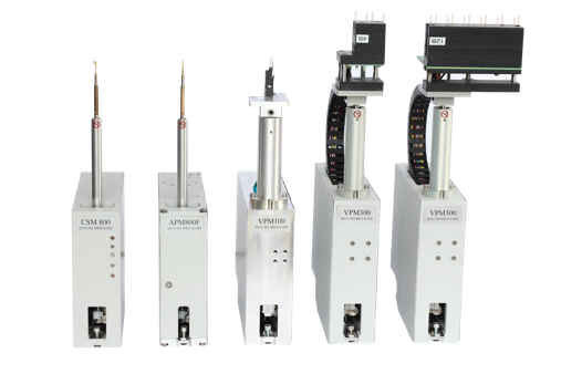
Ultra-Accurate Probing & Positioning System
Flying probe and in-circuit testers (ICT) are used to test printed circuit board assemblies (PCBAs) to ensure quality and functionality.
However, they have some differences in operation, flexibility, and cost-effectiveness.
A flying probe tester is a fixtureless testing tool that utilizes multiple movable test probes to contact specific points on the PCB. It measures the electrical properties of components and checks for shorts, opens, or incorrect component values.
In-circuit testers use a custom test fixture, known as a "bed of nails," to make contact with test points on the PCB. In-circuit testers are generally more suitable for medium to large-scale production.
Flying Probe Testers - key points
- No need for custom test fixtures: Flying probe testers do not require test fixtures, making them suitable for low to medium-volume production runs and ideal for prototyping and rapid design changes.
- Flexibility: They can easily adapt to different PCB designs and test complex, dense boards.
- Shorter setup time: generating test programs is usually quick, and Test programs can be updated to accommodate design changes, enabling faster testing turnaround and reducing production delays.
- Lower operating cost: elimination of fixture costs reduces NRE costs, making flying probe testing more cost-effective for prototypes and small to medium production runs.
In-Circuit Testers - key points
- Custom test fixtures: ICT uses custom test fixtures, often called "bed of nails," to contact test points on a circuit assembly.
- Medium to high-volume production: Electronic manufacturers typically use ICT for medium to high-volume production.
- High test speed: In-circuit testers can perform tests faster than flying probe testers, as they can access multiple test points simultaneously, making them suitable for high-volume production.
- Higher initial cost/NRE: The custom test fixtures required for ICT can be expensive, especially for low-volume production or prototypes.
- Longer test development time: Designing and manufacturing custom test fixtures can lead to more prolonged setup times.
- Less flexibility: Any changes in the PCB design may require updates to the test fixture, increasing test preparation time and cost. This makes ICT less adaptable to frequent design changes than flying probe testers.
Production Test Challenges
Tight quality control measures and time-to-market pressures are compelling manufacturing companies to choose effective yet lean test and quality control strategies. Flying probe testers require no test fixtures, have few restrictions on board access, and can test boards with a virtually unlimited number of nets.
They also allow developers to complete test programs in a short time. With the SCORPION FLS980Dxi Flying Probe Tester, manufacturers can stay ahead of their competition and economically ensure product quality by catching defects before their customers do.
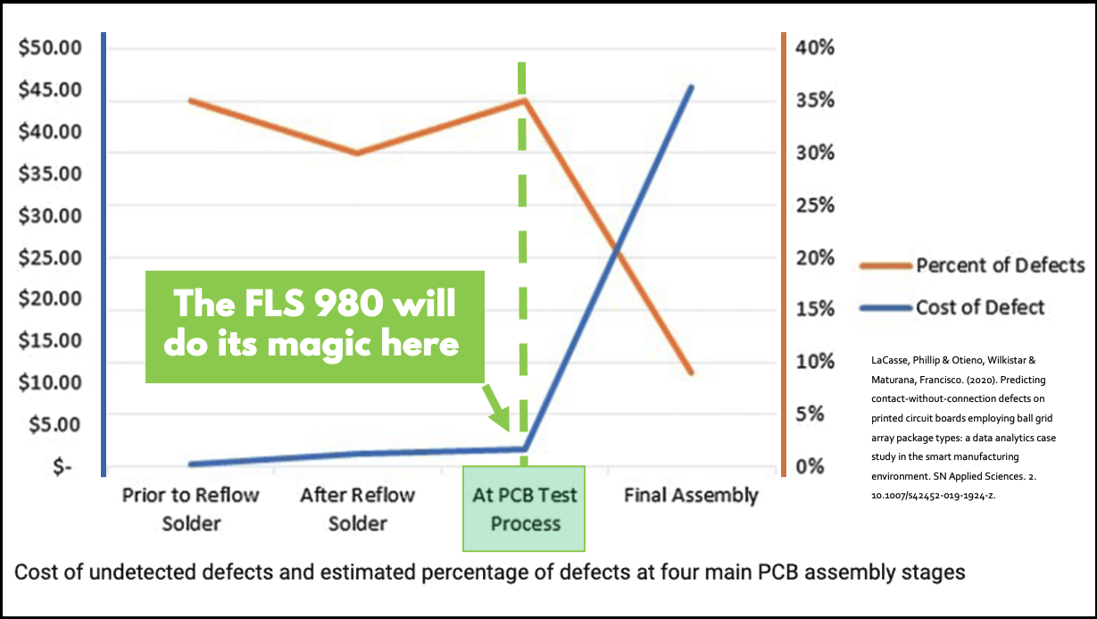
The FLS 980 Catches Defects Before It’s Too Late
The Flexibility of the FLS 980E
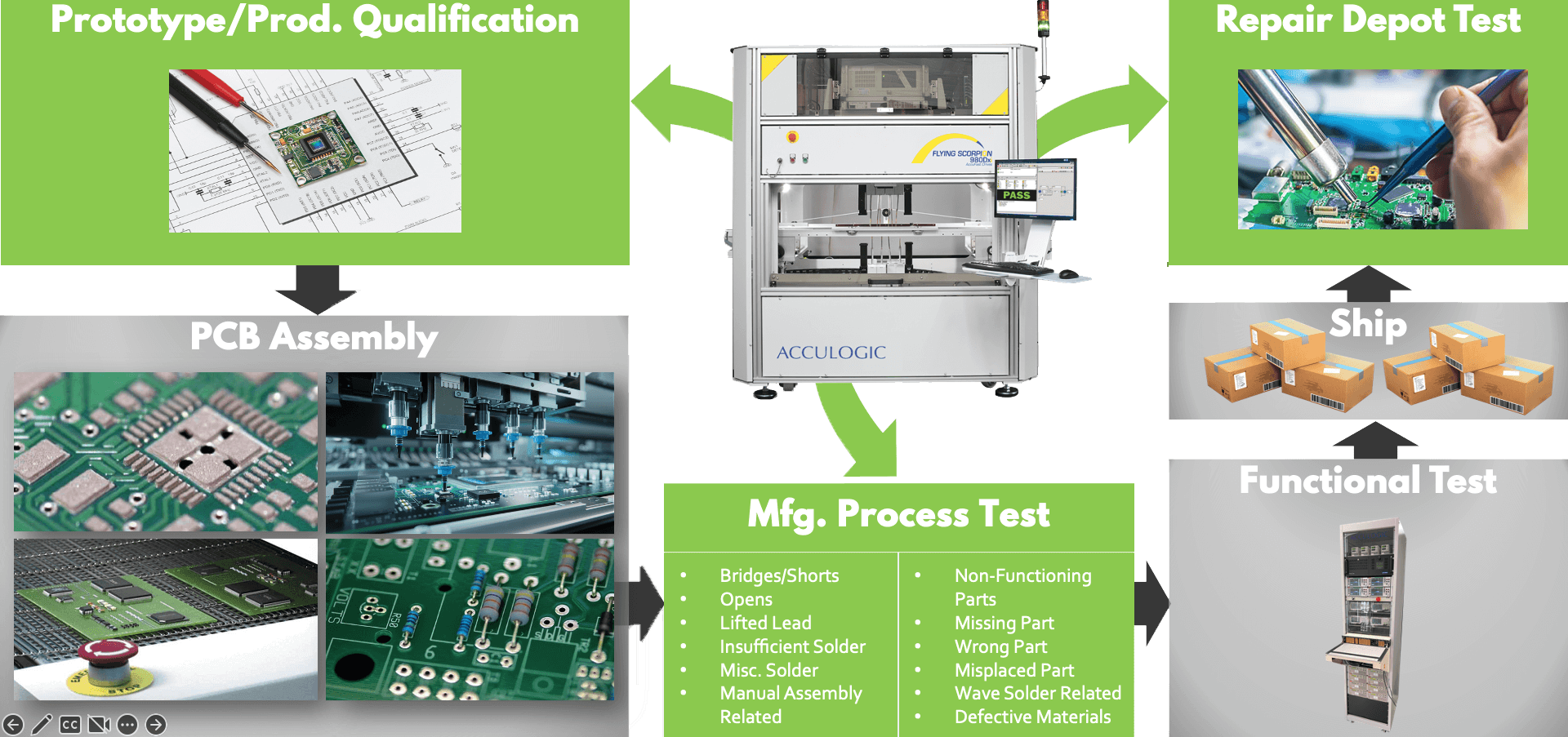
The Scorpion Flying Probe Tester is an effective testing solution that can be used throughout a circuit board's lifecycle. During the prototype testing phase, flying probe testers can quickly and accurately test small production runs, enabling engineers to identify and correct any issues before proceeding with full-scale production. In production testing, flying probe testers can provide high-speed and accurate testing for medium to high-volume production runs. And in repair depot testing, flying probe testers can help diagnose issues with boards that have failed in the field, minimizing downtime and reducing repair costs.
Access Hard-to-Access Devices
Analog Measurement Capabilities
- Resistors
- Kelvin measurement
- Kelvin measurement w/ two test points
- Capacitors
- Inductors
- Diodes, Zener diodes
- Transorbs
- Transistors
- FETs
- Optocouplers
- Thyristors
- Triacs
- Relays, precision relays relay timing
- I-V / V-I curves
- Voltage measurement
- Current measurement
- Filter transfer functions
- Quartz oscillators’ ability to oscillate
- Presence of very small inductances & capacitances
- Power nets, proximity, adjacent, with reference to a net
Vectorless Testing
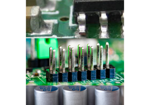
Boundary Scan is very good at testing for IC shorts on nets that have boundary scan drivers, and it is also very good at detecting IC opens on boundary scan nets that have at least one boundary scan driver and one receiver. If memory devices are connected to scannable parts, they will also have boundary scan coverage.
Using a combination of digital boundary scan stimulus and analog flying probe voltage measurement can be used to test the functionality of certain types of circuits, such as A/D and D/A converters and voltage references.
Power-up, Functional & RF Testing
Several sources can be used to power up a UUT inside the FLS980 tester. The ability to power up and flexibly control the UUT allows for functional block testing of onboard power generation circuits, operational amplifier circuits, and simple voltage tests. The UUT power supplies have standard current and voltage monitoring capabilities, which can be used to limit or sample board draws under different load conditions. This flexibility in powering the UUT allows for more extensive test coverage and can help ensure that the device or system being tested is functioning properly and meets the necessary specifications.
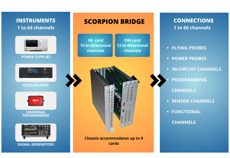
The Acculogic FLS980 Flying Prober enhances circuit board test and inspection capabilities with the introduction of the new Scorpion Bridge.
The Scorpion Bridge module enables test engineers to quickly boost their test coverage and design complete test cycles at the lowest cost.
How? The Scorpion Bridge provides the capability to connect 64 channels with individual testing capabilities to 64 probes on fully automated shuttles capable of on-the-fly transition from test to test with precision placement on the test location.
So, connecting a diverse range of external instruments (such as multimeters, signal generators, programmers, oscilloscopes, and more) to the FLS980 system is inexpensive and quick.
The FLS980Dxi flying probe tester can be combined with a variety of oscilloscopes to perform high-speed RF board testing.
On-Board Device Programming

Optical & Thermal Inspection Capabilities
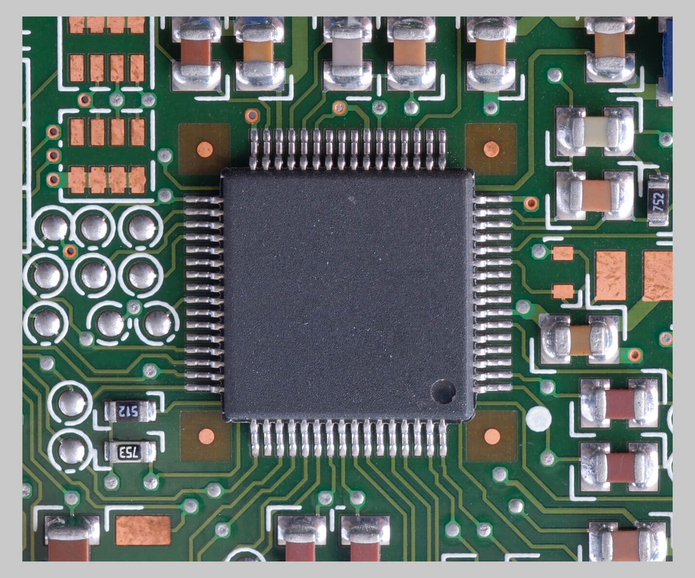
Automated Optical Inspection & Microscopy
LED test
Thermal profile verification
LaserScan
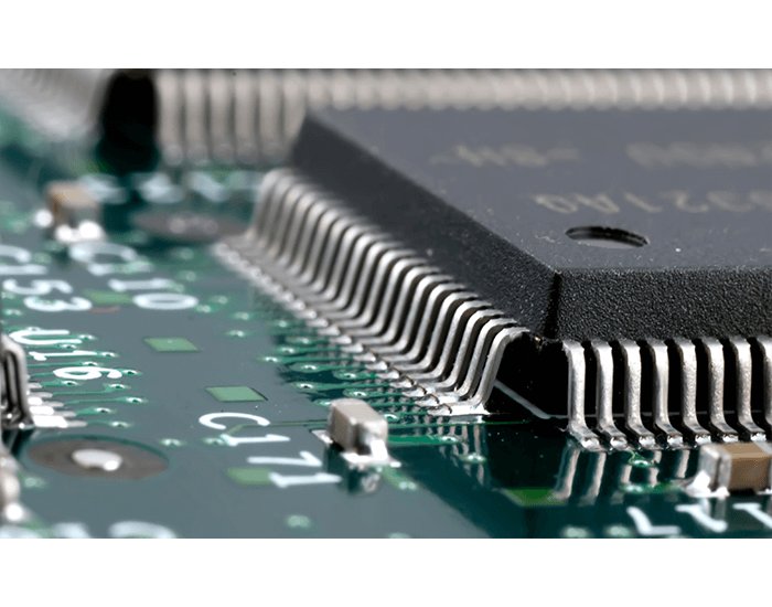
LaserScan will map the board's z-height in as many locations as the user requires, to accurately determine the position of the UUT to within +/- 50 micrometers in the z-axis. So, LaserScan prevents any probing inaccuracies resulting from board warpage.
Flying Fixture
A small Bed of Nails mounted on a shuttle is used for:
INTEGRATOR Operating Software
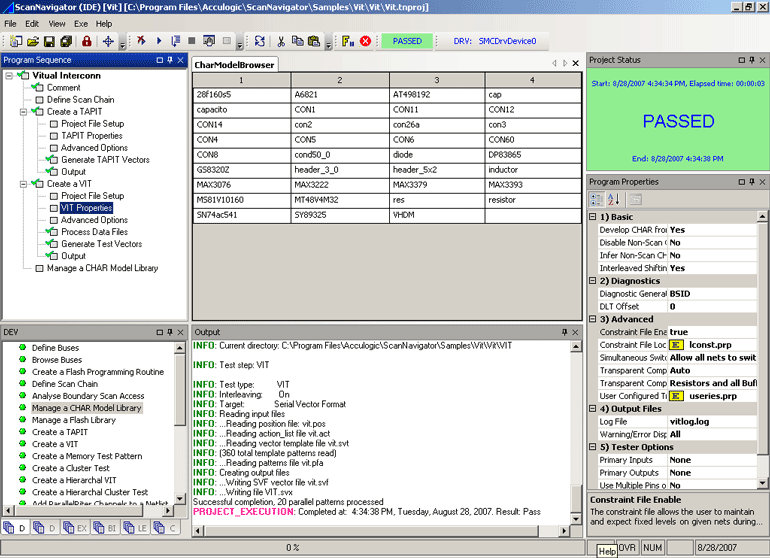
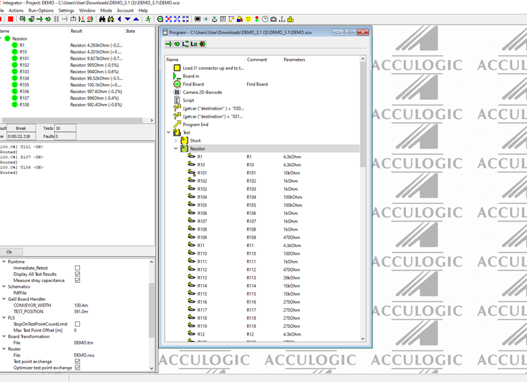
Test program generation for the FLS980 test platform is highly automated, simple, and intuitive. The automatic test program generator and operating software (INTEGRATOR) manages all aspects of test program and moves you quickly from test program development to production test deployment.
Reverse Engineering
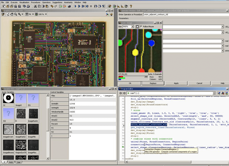
The FLS980DXi is an automated low-cost alternative to manual or semi-automated reverse engineering methods.
| Item | Specification | Value [mm] |
| Fine Pitch Probe Tip* | Thickness at the tip: Length: |
1 44.9 |
| Ultrafine Pitch Probe Tip | Thickness at the tip: Length: |
0.65 48.1 |
| Low Force Rounded Tip | Thickness at the tip: Length: |
0.65 46.9 |
| Cup Probe Tip | Thickness at the tip: Length: |
1 45.1 |
| Standard Probe Tip | Thickness at the tip: Length: |
1 45.1 |
| Chisel Head | Thickness at the tip: Length: |
1 46.9 |
| RF Signal Probe Tip | 2 Pin Head |
Frequently Asked Questions
Acculogic’s XMatic™ software is a fully integrated solution that allows users to transition from design to test and inspection quickly.
With its fast, user-guided nail/probe selection routine and complementary interactive tools, XMatic offers complete flexibility and control during fixture design and flying probe selection.
XMatic automatically generates output files for most commercial In-Circuit, Flying Probe, Boundary Scan/JTAG testers, and AOI machines.
- Support for most commercial CAD formats, including GENCAD, IPC-356, and ODB++, just a few commonly used examples
- Support for all popular ICT, MDA, Flying Probe, and X-Ray Systems
- Net, graphics, and component information is automatically extracted from the CAD files
- Support for both Gerber-D and Gerber-X formats.
Yes, all systems come standard with a pass-through SMEMA compliant conveyor system.
High-resolution fiducial detection cameras, precise lighting, and advanced image processing software guarantee accurate and repeatable detection of fiducial marks on the Unit Under Test and correct compensation for any offsets.
Once the camera system locates the board in the X and Y planes, the LaserScan Module is used to complete the 3D contour map of the board in the Z-plane.
The electronic measurement system relies on precision circuits and components for reliable and repeatable measurements.
Integrator Pro, the operating software system of the FLS980, with sophisticated motion control and measurement algorithms, ensures robust and repeatable operation.
Yes, the tester can do this in 3 ways:
- PolScan (sensor)
- PoleTest (electrical contact)
- Optically
1. ChipScan (Patented) - using the protection diodes built into the Digital IC parts. These limits are very user-programmable and limit the potential for device damage. As all the device power rails are defined, there is little change to stimulate at unsafe levels.
2. CScan - Capacitive Coupling setup using the standard test probes as sensors that hover over the bond wire. 200mV AC stim is placed on the net as the source.
3. Power Up Boundary Scan test driven by Acculogic's ScanNavigator.


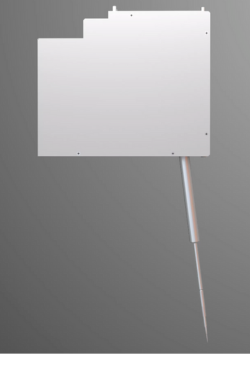 General Probe Module