Device Programming During In-Circuit Test
Programming pods are widely used in manufacturing, particularly during the early stages of firmware development for new products.
The in-circuit test (ICT) station is the best point for programming a board assembly for the following reasons:
- All structural tests have been completed
- There is easy access to the programming header
- Programming pods can be seamlessly integrated into an ICT fixture.
- The next test station is typically the functional or end-of-line test station, where all programmable devices must have firmware installed.
However, challenges in performing device programming at the in-circuit level include:
- Difficulty when the boards are panelized
- Lack of easy access to push buttons and displays
- The need for automation with minimal or no operator intervention
- Programming pods need to be loaded with new firmware from time to time.
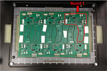
For a customer project, we faced all the challenges listed above. The project required programming 2 distinct programmable devices on each board in a PCB panel containing six boards.
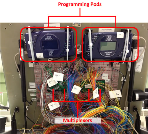
Our solution used two programming pods (P&E Micro Cyclone Pro programming adapters) with multiplexers. We used two multiplexer boards controlled through the in-circuit test program to overcome the panelized board issue.
Since there were six boards in each panel, each multiplexer was responsible for programming three boards.
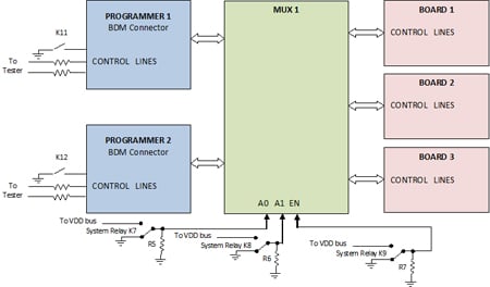
Cyclone Pro programmers are easy to use. As soon as the firmware is loaded, the user only needs to press the “START” button and monitor the “SUCCESS” and “ERROR” LEDs. To automate the process, we decided to "wire" the control lines (START button, SUCCESS and ERROR LEDs) to the ATE system, so controlling the process would be through the ICT program without operator intervention. After sending the “START” command, the test program monitors two LEDs for the result.
If the “SUCCESS” LED turns on, the test program will send a “Programming PASS” message to the screen; otherwise, the result is a fail, and the screen will show “Programming FAIL.”
To upload the latest firmware into the programming pods, the test fixture incorporated 2 USB connectors, each of which was connected to one of the programming pods. This allows a test engineer to quickly and easily upload newly released firmware through the USB port to the pods. A general overview of the pods and multiplexers inside the test fixture is shown here.